Assumptions
Since we are only operating in 2 dimensions, we make some assumptions that allows for simple calculations of motion.
1. We assume the angles used are near equilibrium. (Hover state)
2. The quad copter is small. (Agile)
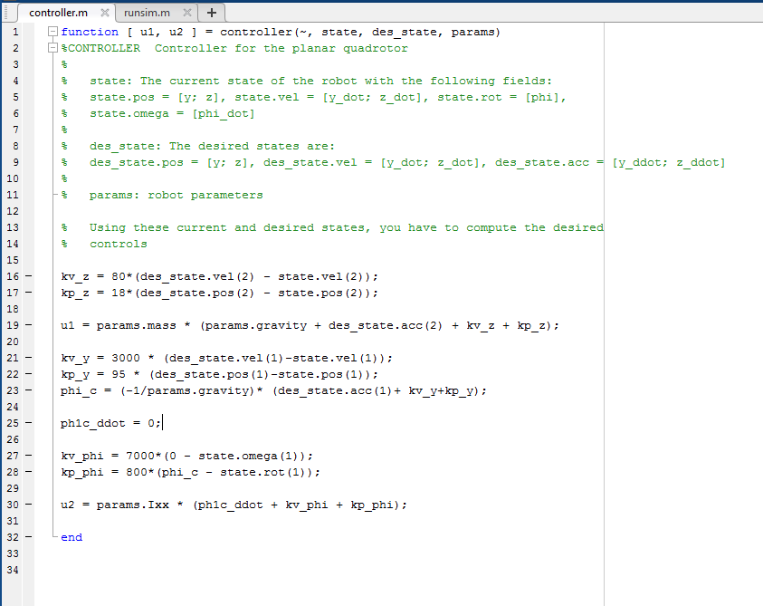
U1.
The value of u1, represents the amount of thrust needed to overcome the mass of the quad copter by determining the amount of error between the current position and desired position. This can be calculated with this formula: u1 = mass * (gravity + z_ddot + kv_z + kP_z)
Variables
params.mass: The total mass of the quad copter.
params.gravity: -9.8 m/s^2.
des_state.acc(2): The double derivative of our z acceleration; also known as z_ddot.
(Remember acceleration is the rate of change of velocity[m/s] over time so m/s^2)
The below two variables are used to "tune" the PD controller to account for the error in the system for the z axis. (over/under compensation)
kv_z: The derivative gain dampens rapidly increasing inputs. This higher the derivative gain the stronger the system reacts to error.
kp_z: The proportional gain determines the speed at which the system reacts to change. Larger inputs have a possibility to cause reactions too quickly which will make the system unstable.
U2.
The value of u2 represents the angle at which the quad copter needs to be in order to move the correct direction by determining the amount of error between the current orientation and the desired orientation. This can be calculated with this formula: u2 = Ixx * (phiC_ddot + kv_phi + kp_phi)
Variables
The below two variables are used to "tune" the PD controller to account for the error in the system for the y axis. (over/under compensation)
kv_y: The derivative gain dampens rapidly increasing inputs. This higher the derivative gain the stronger the system reacts to error.
kp_y: The proportional gain determines the speed at which the system reacts to change. Larger inputs have a possibility to cause reactions too quickly which will make the system unstable.
The below two variables are used to "tune" the PD controller to account for the error in the system for the angle of orientation. (Remember our assumptions above, this angle will be close to 0)
kv_phi: The derivative gain for the angle of orientation. The higher the value the stronger the system will react to error.
kp_phi: The proportional gain for the angle of orientation. The higher the value the quicker the system will respond to error.
phiC: PhiC is the amount of error between the current orientation and the desired orientation accounting for gravity and acceleration. This can be calculated with the following formula: (-1/gravity) * (y_ddot + kv_y + kp_y). *Note y_ddot is the 2nd derivative of y (acceleration in the y direction)
phiC_ddot: Our above assumption of small angles near equilibrium allows us to assume 0 for this value.
params.Ixx: This is the inertia of the current frame.
Tuning
| Parameter | Rise time | Overshoot | Settling time | Steady-state error | Stability |
|---|---|---|---|---|---|
| Decrease | Increase | Small change | Decrease | Degrade | |
| Decrease | Increase | Increase | Eliminate | Degrade | |
| Minor change | Decrease | Decrease | No effect in theory | Improve if small |


(Source)
There are many different methods of tuning a PID controller; the most obvious being through trial and error. Using the above table, you can manually tweak the values of Kp, Ki (if implemented), and Kd in order to adjust how the quad copter reactions to over/under shoots. In my assignments for Coursera, I tuned the controller manually through trial and error but when I build a quad copter in the coming series; I will use a tuning algorithm.
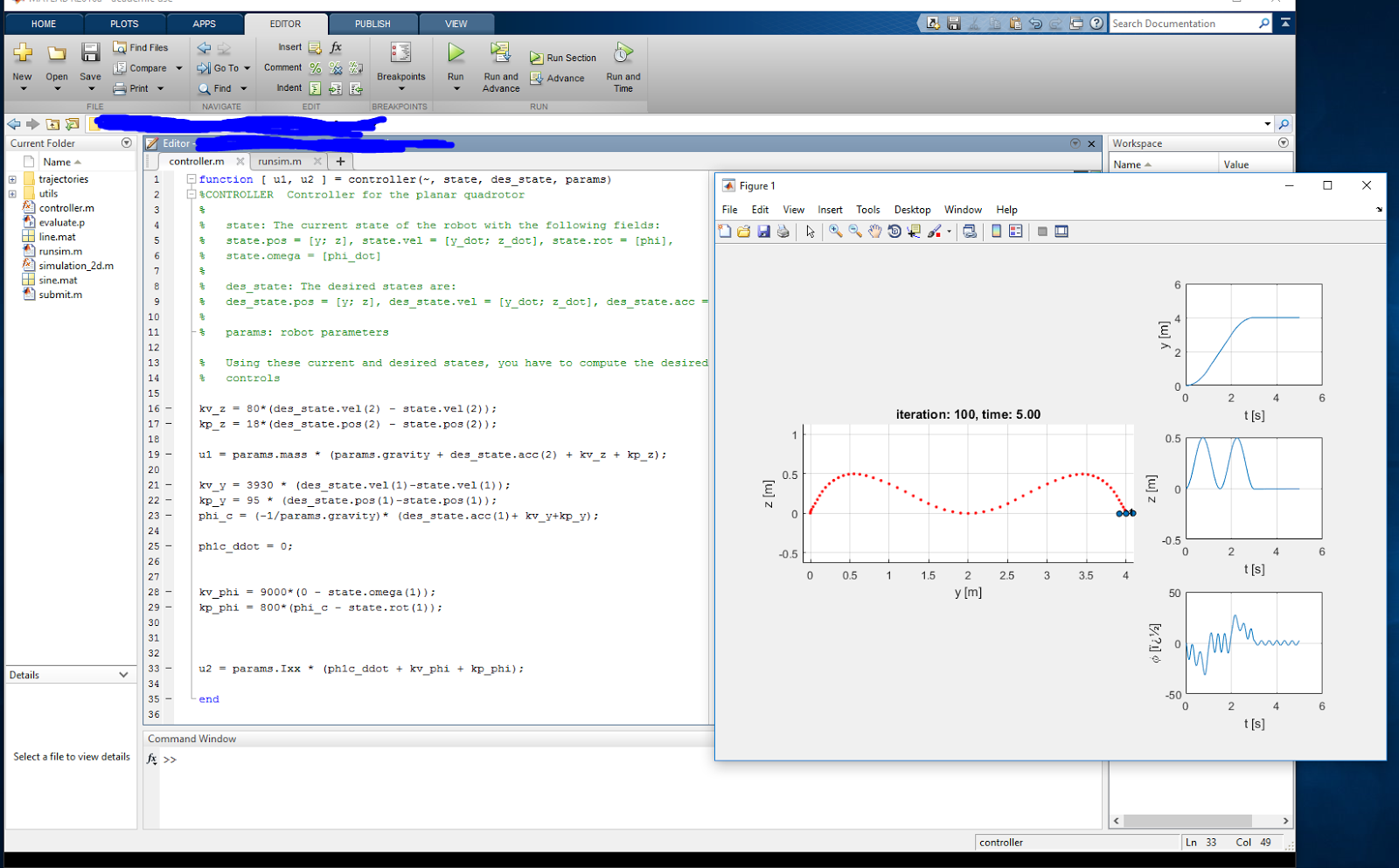
Results
(Straight Line Trajectory)

(Sine Wave Trajectory)

Areas of Improvement
There are two improvements I would make to the controller.
1. Add the integral variable to the controller. This will help with error regarding unknowns such as wind resistance or other unknown variables.
2. We are only operating in 2 dimensions so this does not really model the real world. Adding the 3rd dimension will allow us to model real world movement and facilitate the actual building of a real quad copter.