Saturday, October 15, 2016

Hybrid Application Development

I recently installed Ionic2 and MongoDB so I can begin to familiarize myself with the new world of hybrid application design. I chose Ionic because it is currently the leader in front end standardization for mobile (iOS and Android) as well as web applications. It uses Cordova to build the application for the desired mobile platform which makes development easy since I only have to code everything once then deploy to all environments. MongoDB is a SQL-less database technology that, instead of storing data in rows and tables, data is stored in a JSON format which allows for easy schema modification and scaling for growing applications. I chose this because, as I am building this app on the fly, I do not necessarily know exactly every data point that needs to be stored upfront. While working through some of the finer points, the below will outline some of the issues that I encountered that aware not necessarily intuitive so I feel they should be documented somewhere.

Ionic 2


In order to install Ionic, we need to install node.js. One thing to note here, we normally always install the latest version of software and it normally works but sometimes node can be fickle and be really buggy in latest versions. I suggest picking a version that is a few versions behind the latest to ensure the major bugs are worked out and patched; at the time of writing this blog, I am using v6.1.0.

There are two Command Line Interface (CLI) commands that I find very useful when developing with Ionic; they are "--dev" and "--save". --dev is currently deprecated in v6.1.0 and is replaced with "--only=dev" but the functionality remains the same. This command recursively fetches node packages which means it pulls all dependencies along with the parent package. This is incredibly useful for new developers who need to set up a new environment and might not have the granular package detail as existing environments. An example of this, on Windows, is as follows: "npm update --dev" or "npm update --only=dev".

The second command is "--save". This command pulls the plugin AND adds a reference to the plugin in your config.xml file which contains all plugins your project is using. Many times while developing we might want to test some plugin but not actually save it so we can omit the "--save" and ensure it is not coupled with the project. An example of this, on Windows, is as follows: "cordova plugin add cordova-plugin-facebook4 --save".

Command Prompt


When I first started developing in Ionic I used a non administrator command prompt which eventually led to much frustration because it would serve me errors that had little support on the internet. It took me a little time to discover that these errors were not caused by any code or setup problems but rather the fact that I installed/ran Ionic2 with this non administrator command prompt. Make sure when starting up a command prompt, that you open it with administrator privileges otherwise you will encounter errors and become frustrated with it not working.

Conclusion


I learned a ton about the beginning stages of building a hybrid app over this week and I hope to continue this learning by extending it to native plugin integration such as Facebook / Google+ / Twitter authentication and database integration. One theme that continues to pop up while working with all these technologies is the difficulty in learning new software. Every time there is something new, it is inevitable that we will encounter hardships that feel impossible, but if we can break the problem down and understand its parts, we will eventually solve the problem and grow our knowledge continually.

As always, feel free to leave a comment or question. Happy programming!

Saturday, October 1, 2016

Click Events and Components

Looking Back and the Road Ahead


It is the start of my third month from the start of this blog's and I am pleased with my progress so far. Looking back and remembering all the things I have done up until now is very satisfying. Here is to another three months and more!


Click Events


In any modern game, the user needs to be able to interact with objects they see on the screen whether it is with a mouse, controller, or touch. In Unity, MonoBehaviors extend specific events such as "OnMouseDown() and OnMouseOver()" and when a collider component is attached to the GameObject the events will trigger the predefined methods if specific requirements are met. It is important to note that if your GameObject DOES NOT have a "Mesh Collider" component the events will not be fired. Another caveat about the above two methods is OnMouseDown() is only useful for left mouse button clicks, however, the OnMouseOver() method is able to capture all three mouse button inputs. An example can be seen below of this behavior.

(On this example I click each mouse button four times but only the left click is caught.)


Distinguishing the differences between these two methods was painstaking since there is no documentation of this behavior and many stack overflow answers referenced older versions of Unity which was not helpful. Hopefully this will help someone in the future not make the same mistakes and save them some time. Now that I am able to capture left and right mouse clicks I can create and destroy cell tiles with just a few clicks!


Components


Another crucial part of Unity are Components as they are the building blocks of all things and if you want to do anything useful you will need to understand Components and how they affect GameObjects. Currently I am only using a few Components, such as colliders and Scripts, in order to keep things simple.

Game Map


The first script I created is the MapEditorScript which holds the relevant information pertaining to the whole game map such as cell stacks, units, and other map related logic. From the above image you can see the 5x5 grid of hexagons and in order to display those I need a few things defined. First, I need a prefab; creating one is easy if you follow these steps found in the documentation. In order for my script to run, it needs to be attached to a GameObject but before the map is created there are no GameObjects in the scene. This obstacle can be overcome by creating an empty GameObject and attaching the MapEditorScript to it. Once the scripted is added, I can run the preview and see the map generated at run time.


Cell Stack


I want to be able to click on each tile and create a new tile on top of the existing tile. To do this, I need some data structure to hold the stack of cells to be rendered and handle events on each click. I made a CellStackScript which handles everything related to the Cell Stack such as creating/destroying tiles which can be seen below.


The bulk of the work is done by the CreateNewCellTile() method which instantiate's the prefab, sets the position, orientation, and parent, adds the CellTileScript, and finally pushes the newly created tile onto the Cell Stack. This sequence of events allows me to click on each cell stack individually and grow and trim each stack separately.


Cell Tile


I mentioned above about adding the CellTileScript to the children cells. Before this script is added, only the very first tile (the bottom tile) has click events which is not realistic in this scenario especially when tiles begin to grow in size and hide tiles that are behind the stack. We must attach some click event to each child that allows it to create a new tile in its Cell Stack. By giving each Cell Tile the reference to the parent cell (bottom most tile), we enable the ability to call back to the parent and create or destroy cells with click events on each tile in the stack. 


Conclusion


The topics discussed above took some time to understand and I ran into many road blocks along the way. Fortunately I resolved these through some creative problem solving and deductive reasoning. I now understand how Components fit into the Unity framework and moving forward will begin to utilize them more often. Click events will be used quite frequently since it is the main method the user will interact with the game world.

The next thing I want to accomplish is to add a few textures dynamically to the tiles in order to give the them a bit more character as well as be more visually appealing. Lastly I want to modify the camera so I can move around and rotate, allowing me to view all sides of the map.

As always, feel free to leave a comment or question. Happy gaming!

Tuesday, September 20, 2016

Back to the Basics

To begin the process of building this game I needed to decide a few things.
  1. In what framework am I going to build this game. 
  2. What program will I use to create models. (2D or 3D)
  3. In what language will the scripting be written.
Another important thing I need to consider is cross platform compatibility. I personally would like for this game to be run on many different platforms with as little effort as possible. Taking into account all of the above I decided to work with the free game engine Unity and the free modeling software Blender. Now both of these frameworks are advanced tools that are used to create amazing AAA games, but for my purposes I will be using a small fraction of the features in the beginning as I learn.

Blender

The shear amount of features in Blender can cause sensory overload and even the most veteran developer can feel intimidated. When I first opened the application, I had no idea what to do and I almost closed it and quit but I really wanted to build this game so I persevered. The community built around this tool is incredibly helpful and answered so many of my beginner questions that I feel indebted to them.

My first task is to create a simple hexagon that will be used to tile game cells. These hexagons will eventually be textured to look like different terrain types as well as have additional functionality not yet determined. There are a lot of ways to create a hexagon but in my short time with Blender I feel I have found the quickest and easiest solution that is not already a top search result on Google.

Step 1. Open Blender


Step 2. Delete everything in the scene


Step 3. Create a Circle Mesh

Step 4. Modify the Circle properties to have 6 Vertices, set the fill type to Ngon, and set the Location to 0,0,0.


Step 5. Select the model and change to "Edit" mode. Use the hotkey Alt + E to enter "Extrude" mode.
-I gave mine a depth of 0.25.


Step 6. Save the model. (I saved mine with a .blender extension)

Now we have a 3D model of a hexagon that will be the base model for our terrain tiles. Next task on our list is to boot up Unity and get this tile to display in the engine.

Unity

Similar to Blender, Unity offers numerous advanced features that can intimidate a developer.  When things get too chaotic and you feel like you are being discouraged by too many unknowns, take a step back and take some time to go over what you already know. This will help you stay on track while maintaining the vision of your game.

To start off I created a new Unity project and dragged the hexagon I created above into the "Assets" folder. Once in the folder, I clicked and dragged the model into the scene.


This click and drag approach won't work for more complex features such as a map editor so I need to add scripts to the scene in order to achieve some sort of dynamic object creation. The simplest way I was able to do this was by right clicking in the Assets folder and creating a new script; named MapEditorScript.

Double clicking on this script opens in my Visual Studio so I can edit the file. Scripts start out with two functions, Start and Update. From their names it is pretty obvious what they do. Code inside the start method is run once on initialization and code inside the update method is run once per game loop.


Now that the script is created, in order for the script to run it MUST BE attached to a game object. To do this, click the desired script and drag it onto an object in the scene. If this is not done, the script will not run and you will wonder why nothing is working. (It happened to me.) When everything is finished it will look something like this.


Conclusion

This week was spent learning the bare basics of Blender and Unity so I can begin to implement the core features of this game. Now I know how to create basic primitive shapes in blender as well as create a script that allows dynamic object creation at run time. Both of these concepts will be drawn upon heavily moving forward so it is important that I understand them fully.

Next week I plan on adding click detection so I can click on areas in the scene to create new objects. Once I can create new tiles with click events, I can implement logic to allow a user to create a dynamic map on the fly.

Wednesday, September 14, 2016

The New Game!

After working on my quadcopter for a while I decided to branch out and start a new project since I am waiting on hardware. I am fascinated by video games and the process of developing them so I figure making one of my own will be fun and a new learning experience. I always had a few game ideas floating in my head so now is the time to put pen to paper and start developing my very own game!

The Gist

Of all the games I have played, the ones that survive are games that have modding capabilities and a strong community that creates new content. Developers struggle to push out new content for their users in a timely fashion and it always seems that they are never fast enough. This problem can be solved by opening up modding and content creation tools that allows the community to create and share new things. The main focus of this game will be the modding potential and content creation by the community so I will need to create and expose tools that allow players the ability to add new stuff to the game.

What is it?!?

If you have ever played Final Fantasy Tactics AdvanceFire Emblem, or Advanced Wars this is basically a merging of features from each game that I find critical to fun game play. The main game mechanics that I like are as follows:

Final Fantasy Tactics Advanced:
- Dynamic Class System
- Laws that change each maps game play

Fire Emblem
- Permanent Character Death
- Large maps
- Shops in the map instead of ambient merchants available outside matches

Advanced Wars
- Buildings that generate resources and units
- Player specials (e.g. each commander has a separate but unique super move)
- Map Editor

Over the coming weeks and months I will be implimenting these awesome features into a single game and eventually releasing it to the world through some sort of marketplace. I haven't decided if I want to make it a mobile game or PC only. 

Starting Point

Starting off I will be building the map editor first since this is an important part of the game. My vision for this is to allow any player the ability to create a map and expose it to the rest of the community with little effort. The tiles will be hexagons with the sides being horizontal in orientation and can be stacked on top of each other to achieve height effects. I will be using Visual Studio as my IDE and for starters using only Components for the graphics. I have thoughts of moving it to Android and iOS but I will need to research the difficulty and effort needed to perform such a migration.

As always, feel free to post any questions or comments; happy gaming!

Monday, August 29, 2016

Reading Serial IMU Data

Last time we left off, we were able to send data serially to our python client which in turn, published the data to our ROS topic. Since we made a proof of concept (POC) with static values, we should be able to use this functionality to send the data of the Inertial Measurement Unit (IMU) serially. One known thing about IMU's is they are notoriously noisy so the readings from the accelerometer and gyroscope need to be filtered in order to observe meaningful data. Below we will explore one way to read IMU data serially, run it through a complimentary filter, and write to the output buffer.

Reading the IMU

If you remember from an 
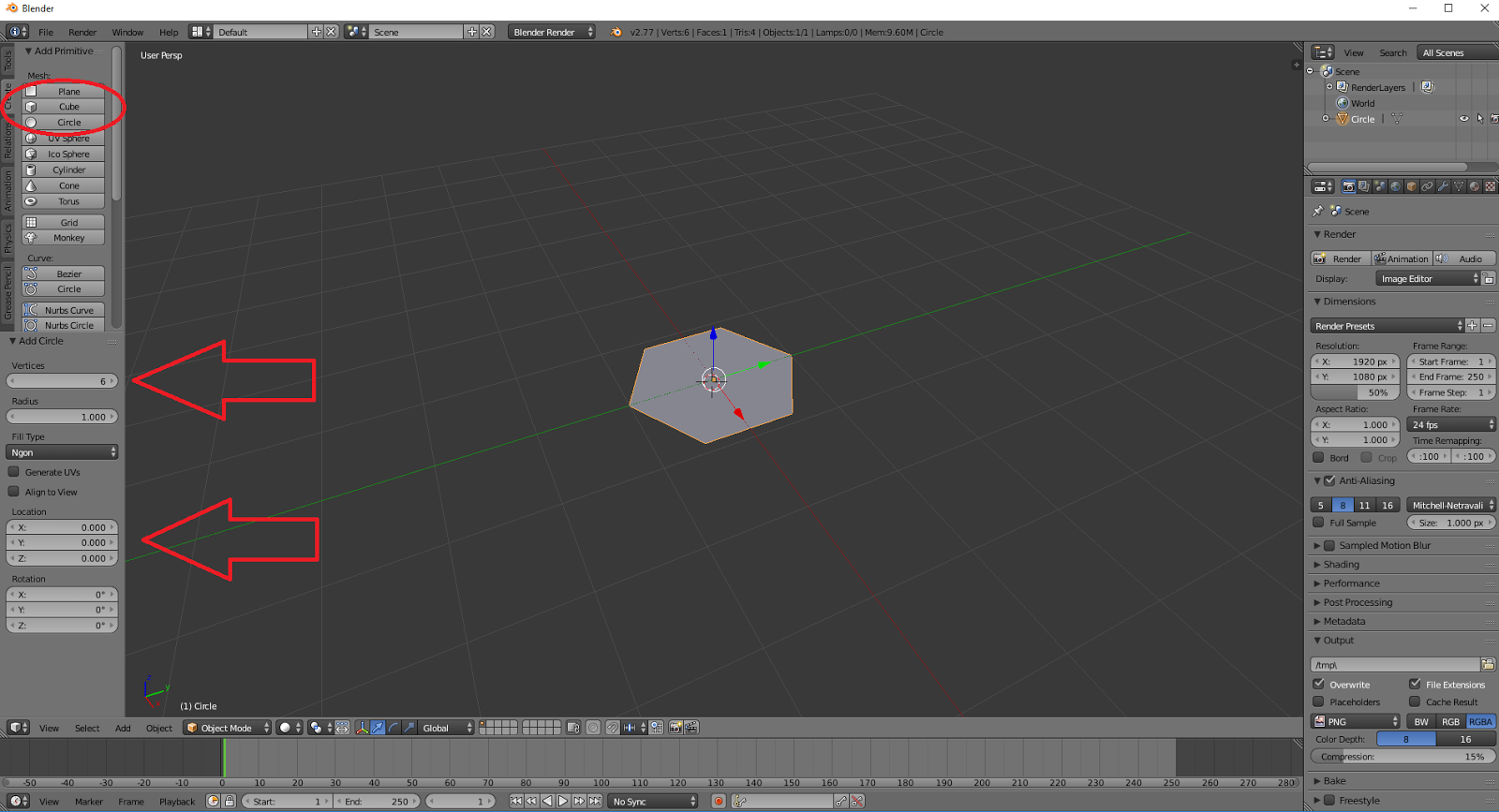
earlier blog post where I listed the sensors I bought, the IMU is a LSM6DS33 3D Accelerometer and Gyro. It includes a 3.3V voltage regulator that allows a range of 2.5. to 5.5V which is nice since the Arduino Pro Mini pulls 5V. Pololu, the website where I purchased the sensors, has a resources section which directed me to a library specifically written for the sensor. Upon reviewing the source on GitHub, I decided this would be a good way to expedite development since the library is very simple and I have no experience reading analog values. After installing the library, an example sketch can be loaded through the Arduino IDE menu.


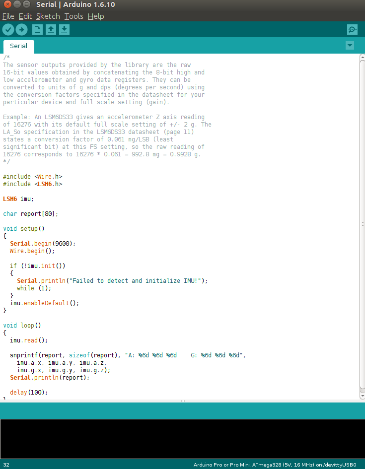
The code on the right is the LSM6 Sketch and it contains everything you need in order to read the data from the IMU. All you need to do now is upload this sketch to the Arduino, make sure the IMU is connected correctly to the Arduino, and to provide power. While the program is running, if you have the serial monitor open, you will see a stream of data filling the screen with readings.

(Note: The stutter in the readings is caused by the Serial Monitor and not the sensor as we will see later when our ROS topic is publishing data in real time without lag.)


Interpreting the Data

The above image shows readings that are not very intuitive at first glance and can scare new hobbyists, hopefully the explanation below will help demystify the numbers and process.  

Accelerometer

The expected values for the accelerometer are X = 0, Y = 0, Z = -1 which just means that there is a downward force of 1 G. For those that might not find the above expected values intuitive, there are two reasons we are expecting these values. First, gravity is always acting, causing us to fall towards the center of the earth (1 G Force or -9.8 m/s^2). Second, since we are modeling the real world the sign (+-) of the Force really only determines the direction the Force is applied. For example, the Z axis represents up(+) and down(-). The accelerometer can also measure different scales of forces but in our case we have set the full scale setting to 2 which means we can effectively measure forces between -2G and 2G.

Now that we have expected values, we can begin to convert the raw readings into actual Forces. Looking at the image above we can take a random value from the 3rd column (Z acceleration force); I will pick -16,642. From page 15 of the LSM6 Data Sheet, we can find the units for the full scale setting of 2, linear acceleration sensitivity, 0.061mg/LSB (milli g's / Least Significant Bit). Taking the raw data and multiplying the sensitivity ratio we get the following:

1. -16,642 * 0.061 = -1,015.162 mg (These units are milli g's)

We need to account for the milli g's by dividing the number by 1000 to get g units.
2. -1,015.162 mg / 1000 mg = -1.015162 g

This value is close enough to -1 that we can dismiss the extra force measured as background noise. The above math can be made more generic so it can be applied to each dimension measured by the accelerometer.

3. Raw Data * Linear_Acceleration_Sensitivity * (1 g / 1000 mg)

If we convert the Linear_Acceleration_Sensitivity value from millig's to g's during setup we can reduce total calculations per iteraiton.

4. Raw Data * Linear_Acceleration_Sensitivity_G = result
(Note: Steps 1 & 2 combined are Step 4)


Gyroscope

The expected values for the gyroscope at rest are 0 dps (degrees per second) for X, Y and Z dimensions because the gyroscope measures the rate of change in angular acceleration. The raw data is measured in mdps/LSB and must be converted in order to be a meaningful value. Again, looking at page 15 of the LSM6 Data Sheet, we can find the angular rate sensitivity for the full gain setting 245 which is 8.75mdps/LSB. (milli degrees per second / Least Significant Bit)

First our angular rate sensitivity is in mdps and we need to turn it into dps.
1. 8.75 / 1000 = 0.00875 dps/LSB (This result is the Angular_Rate_Sensitivity in terms of g's)

Multiply the raw value by the angular rate sensitivity to get degrees per second
2. Raw Data * Angular_Rate_Sensitivity = result

If we calculate some of the values in the above image, we will notice that the results are not 0 and in fact they oscillate between a specific range. This oscillation is due to imperfections in the sensor and must be accounted for by setting a threshold that floors the readings and helps remove the noise. In our case, I checked the data sheet and noticed there is a rate of (+-)10 dps so any readings between -10 and 10 are floored to 0.

Note: The result is in degrees per second but we are reading data from the IMU much quicker than 1 second intervals. To remedy this we need to integrate (sum the data over time) the result by multiplying by the time it took to run the last iteration (delta time [normally in milliseconds]). As soon as we integrate the gyro data (gyroData * dt), we introduce error because our sample size is not continuous which will cause error interpreted as drift; the main reason why we will smooth the data using a complimentary filter.

Complimentary Filter

The idea of smoothing out the data is not new and there is even a standard call the Kalman Filter. While the Kalman Filter is very complex, there is a simpler approach that requires little overhead. (We will be implementing a Kalman Filter in the future, just not right now.) For now, we will use what is called a 
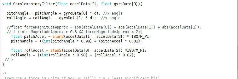
Complimentary Filter:

angle = (angle + gyroData * dt) * 0.98 + (angle of acceleration * 0.02) 


To get the angle of acceleration we can use the arc tangent but this causes problems because quite frequently our divisor will be 0 and we cannot divide by 0. Luckily we have access to the atan2 function which allows us to supply 2 inputs and get an angle representative of the inputs. There are plenty of websites that will explain what the arctangent and atan2 functions are so if you are interested I suggest reading further

(Note: The above code will probably not work copy pasta unless the rest is configured exactly the same.)


(Disregard the linear values as they are debug terms I am using)

We see that at rest the IMU is reading 0 and when disturbed, we get precise readings. Moving forward these values will be fed into a PID controller which will be used to stabilize and move the quadcopter.

Findings

There is very little documentation for hobbyists online at the moment and I am continually scouring the internet for resources but they are far and few between. I think this will be a good opportunity to add to the collective knowledge base of the internet with my findings and hopefully my struggles will make someone else's experience easier. As always, feel free to leave a comment or question. Happy flying!


Tuesday, August 23, 2016

Roadblocks, an Opportunity for Learning

After getting the virtual machine set up, I installed ROS and went through all of the tutorials in order to better understand the framework. In the end, I had a working topic, message, publisher, and subscriber. The examples provided on the ROS website were enough to get a simple application set up and understand how to interact with the framework as well and use ROSSerial to communicate with the simulator; Rviz.


The Hill

Coming from a software developer background, I am not used to hardware constraints. If I need another variable, I just make one. With the Arduino, we only have 32kb of Flash memory, 2KB of which is reserved for the boot loader, 2KB of SRAM, and 1KB of EEPROM so virtual space is at a premium. After finishing the tutorials and making a working example, I decided it is time to use ROSSerial to publish the IMU data so Rviz can simulate. I thought combining the IMU example with the ROSSerial example would produce a desirable result, but in the end it proved nothing but a headache. We will still use ROS but not on the Arduino.


The Battle

As soon as I added a node handler, the 2KB of SRAM dwindled as seen in the picture above. Even with the most basic usage, I was running out of SRAM before I could even do any calculations AND the motors aren't even considered. I looked for other ways to solve this memory problem because it caused syncing problems during sketch uploads. The Arduino gives the capability to store common parameters in EEPROM then queried during run time so I tried to utilize this space to hold the publisher and node handler, since these objects are required globally; unfortunately, they are too large for this reserved space so the search continued. By this time a few days had passed and I decide that the ROSSerial library is too large for the Arduino so I needed to find a different way to send the IMU data to Rviz.


Success

Eventually, writing the data serially became my last option and incidentally, it turned out to be the easiest solution. I read up on Serial Communication and a few other hardware topics that are unfamiliar to me then came up with the simple solution seen below. Arduino exposes functionality that allows us to write data serially with the Serial.write() command and supports strings, arrays, and bytes. The test data is written while, on a port connected to the Arduino, a python client listens and decodes the data to be used by Rviz.


The python script handles everything including initializing the node, creating the publisher, connecting to the Arduino, reading the serial data, publishing the data and printing the data to the logs. This script will be heavily used for simulating data on Rviz which will be the subject of the next blog post. Aside from the script, I also created a launch package for the python client, roscore, and rviz so I no longer need to have a separate terminal open for each. Going forward, new executables will be added to this launch package to make deploying everything easier. Below is an example of the data being sent by the Arduino and received by the python client on the VM.


Lessons Learned

Over the course of the week I spent many hours reading blogs, documentation, and other sources. After countless failed attempts, continuing can be frustrating and somewhat disheartening but by keeping a level head and repeatedly attacking the problem from different angles, I was able to solve the issue AND learn several things in the process. Another important thing I learned is IMU's are prone to drifting errors which requires a remedy. The next item to work on is a Kalman Filter that will allow us to smooth the drift by using a feedback loop.

As always, feel free to leave a comment or question.

Sunday, August 14, 2016

Setting Up Our Development Environment!!!

Parts are arriving daily! Soon we can begin connecting the basic sensors and start getting actual readings. Our goal over this week was to get our development environment setup so we can start reading sensor data on the Arduino Pro Mini.


Sensors1

Environment Setup


Virtual Machine (VM)


We need a development environment that can be isolated from our workstation without being burdensome. A good tool that satisfies this requirement is a virtual machine. Software is capable of emulating hardware, allowing for sand-boxed operating systems within your current workstation. There are several vendors of virtual machines but I normally stick with Oracle VM VirtualBox due to already being familiar with the software. Once installed, we can download an operating system image and use it to install a fresh version on the VM so we can begin to setup our dev environment.

Operating System (Ubuntu)


In order to utilize the VM, we will need an operating system to run. In this series, I will use Ubuntu version 16.04 as it is recommened for some of our third party libraries. Install Ubuntu onto an instance of a VM and follow the on screen instructions. After some time, the software will be installed and we can move on to the next step.

IDE (Arduino)


Our programs need to run on the Arduino Pro Mini and Raspberry Pi Zero. In order to write program that CAN run on those electronics, we need to install the latest Arduino IDE. Take note, I ran into issues installing the latest using "sudo apt-get arduino" so I did some searching and found a workaround. Get the latest IDE installed and we can move on to installing some third party libraries that will make development much easier.

Third Party Libraries (ROS)

ROS is a framework for creating robot software. We will use the concepts provided to design our own framework for communication between all of the sensors. In order to utilize the ROS communication framework on our Arduino, we need to use the RosSerial library. This will expose ROS functionality on the Arduino and make development and integration of all the sensors painless. The first sensor we will be testing is the accelerometer/gyro and luckily, someone already wrote a lean library for reading the raw data.

Goals


Our goals for this week are to get a working, visual, simulation of the accelerometer/gyro in ROS which will mean we need to complete the tutorials. Also, research quaternion math and how it applies to orientation.


Extras!


I got super excited while setting up my environment that I made a little surprise for you! Here is a sneak peak at what all of the above will look like.