
(Helix Pattern)
Thrust
Traditionally, the quad copter's frame and propeller are rigid which means the Force generated by the propeller is always perpendicular to the quad's frame. Locally we define this perpendicular angle to be the z axis.1 Knowing this, the minimum Force needed to either hover or rise can be calculated using the following equation:
Force = Mass * Acceleration
Our mass is the mass of the quad copter and our acceleration is gravity plus any additional force we want to add. Since gravity is always acting on our quad copter in the downward direction
(-9.8 m/s^2), we need to counter this force by providing at least this much acceleration upwards in Thrust. If we wanted to rise in altitude, we would need to provide more Thrust than 9.8 m/s^2. The equation to calculate the amount of acceleration needed can be found below.
Acceleration= Gravity + Desired Acceleration in z direction (z_command)
z_command = desired acceleration z
+ kd_z * (desired velocity z - current velocity z)
+ kp_z * (desired position z - current position z)
If we look at the previous post, this is the same equation except, instead of using the y axis we are now using z; for reasons explained above. The kd_z, derivative and kp_z, proportional terms, help reduce the amount of error in the system by modifying the speed, proportional gain, and rate, derivative gain, at which the quad copter reacts to change.
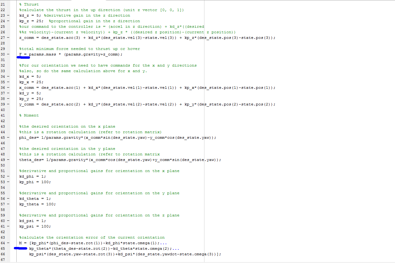
In the end, our Force equation looks something like this:
Force = Mass * (Gravity + z_command)
The other dimensions, x and y, are calculated the same way but their values are not used in the Thrust calculations, rather they are used to calculate Orientation. Note that each calculation has its own derivative and proportional terms with respect to their axis.
x_command = desired acceleration x
+ kd_x * (desired velocity x - current velocity x)
+ kp_x * (desired position x - current position x)
y_command = desired acceleration y
+ kd_y * (desired velocity y - current velocity y)
+ kp_y * (desired position y - current position y)
Orientation
The second component to 3D movement is orientation. We have 3 types of orientations we can apply to the quad copter; pitch rotating on x axis, yaw rotating on z axis, and roll rotating on y axis. Our output for this term is going to be a 1x3 rotation matrix representing the x, y, and z rotations; phi, theta, psi respectively. The x and y rotations have their equations described below but the z calculation is a simple difference to determine the yaw.
Pitch
phi_command= 1 / Gravity
* (x_command * sin(desired yaw rotation)
- (y_command * cos(desired yaw rotation)
Roll
theta_command= 1 / Gravity
* (x_command * cos(desired yaw rotation)
+ (y_command * sin(desired yaw rotation)
We use the desired yaw rotation (z angle) because both the x and y axis need to be rotated over the z axis. This allows for some measure of control when dealing with rapid movements. Now, the above equation only calculates the raw angle needed so we will need to apply some error smoothing in order to reduce choppy movement.2
Orientation = [kp_phi * (phi_command - current phi) - kd_phi * current angular accel x
kp_theta * (theta_command - current theta) - kd_theta * current angular accel y
kp_psi * (desired yaw - current yaw) + kd_psi * (desired angular accel z - current angular accel z)];
When everything is put together it will look something like this.
Conclusion
Adding a layer of trajectory planning on top of the PID controller gives the quad copter the ability to perform maneuvers as seen in the images below. This Coursera class taught me so much about how a quad rotor maneuvers and the calculations needed in order to program a flight controller. In the coming weeks, I will begin the journey and build my own quad copter from the ground up. This includes building the hardware as well as programming the flight controller and autonomous behavior.

(Straight Line)
(Waypoints)
More Information
1. I come from a background of graphics programming in OpenGL and the coordinate system that is traditionally used in that context has the z axis projecting out of the screen, y pointing upwards, and x being horizontal. In the Coursera class I am taking, the coordinate system used is different so it is worth noting the difference. In the context of quad copters, z is pointing upwards, y is projecting out of the screen, and x is still horizontal.
2. Note that each angle has its own derivative, kd and proportional, kp term.
No comments:
Post a Comment